Alpha Clipping
Opaque 오브젝트라 할 지라도, Alpha Clipping을 이용하면 Alpha 값을 이용 할 수 있다.
Texture 자체에 Transparency 한 부분이 있다면, Alpha Clipping을 쓸 수 있다.
Alpha Clipping이란, 커스터마이징 가능한 임계값 (Threshold)으로써 알파 값을 사용해 픽셀을 Cull 할 수 있게 해주는 기법이다.
Alpha Cutout in HLSL
Shader "Lucid-Boundary/Tranparent_AlphaCutout"
{
    Properties
    {
        _MainTex ("Texture", 2D) = "white" {}
        _BaseColor("Base Color", Color) = (1, 1, 1, 1)
        _ClipThreshold("Alpha Clip Threshold", Range(0, 1)) = 0.5
    }
    SubShader
    {
        Tags
        {
            "RenderType"="Opaque"
            "Queue" = "AlphaTest"
        }

        Pass
        {
            HLSLPROGRAM
            #pragma vertex vert
            #pragma fragment frag

            #include "Packages/com.unity.render-pipelines.universal/ShaderLibrary/Core.hlsl"

            struct appdata
            {
                float4 vertex : POSITION;
                float2 uv : TEXCOORD0;
            };

            struct v2f
            {
                float2 uv : TEXCOORD0;
                float4 vertex : SV_POSITION;
            };

            texture2D _MainTex;
            SamplerState sampler_MainTex;

            CBUFFER_START(UnityPerMaterial)
                float4 _MainTex_ST;
                float4 _BaseColor;
                float _ClipThreshold;
            CBUFFER_END


            v2f vert (appdata v)
            {
                v2f o;
                o.vertex = TransformObjectToHClip(v.vertex.xyz);
                o.uv = TRANSFORM_TEX(v.uv, _MainTex);
                return o;
            }

            float4 frag (v2f i) : SV_Target
            {
                float4 col = SAMPLE_TEXTURE2D(_MainTex, sampler_MainTex, i.uv);
                float4 outputColor = col * _BaseColor;

                if(outputColor.a < _ClipThreshold) discard;
                return outputColor;
            }
            ENDHLSL
        }
    }
}
Fragment 함수부분만 보자.
ClipThreshold 보다 Alpha값이 낮으면 그냥 버려버리도록 구현된 HLSL 코드이다.
그 결과는 다음과 같다.
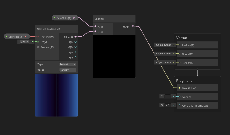
Alpha Cutout In Shader Graph

Shader Graph 내에서 Alpha Clipping을 체크하자
Fragment Shader 부분에 Alpha 와 Threshold 부분이 생긴걸 확인 할 수 있다.
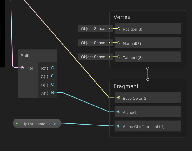
그럼, 그 값에 Float 값을 넣어주기만 해도 끝난다. 무척 편하다.
Alpha Clipping은 플랫폼에 따라 성능이 Transparent 오브젝트를 사용하는 것보다 빠를 수도 느릴 수도 있다.
테스트 해보며 잘 선택하자.
Dithered Transparency With Alpha Clip
Transparent 오브젝트는 Depth 별로 정렬도 해야하고, Blend도 해야하고, 여러모로 Opaque에 비해서 연산량이 높은 편이다.
그래서 만약, Opaque의 이점을 가진채로 Transparent의 성질도 가지면 정말 유용할 것이다.
Dithered (잡음) Tranparency Effect는 Screen-Door Transparency로도 알려져 있으며 위 성질을 갖고 있다.
Alpha Clipping을 렌더링하면서 픽셀들을 특별한 패턴 안에서 Cull 할 수 있도록 한다.
HLSL을 통해 우선 구현해보자.
Shader "Lucid-Boundary/Tranparent_DitheredTransparencyEffect"
{
    Properties
    {
        _MainTex ("Texture", 2D) = "white" {}
        _BaseColor("Base Color", Color) = (1, 1, 1, 1)
        // _ClipThreshold("Alpha Clip Threshold", Range(0, 1)) = 0.5
    }
    SubShader
    {
        Tags
        {
            "RenderType"="Opaque"
            "Queue" = "AlphaTest"
        }

        Pass
        {
            HLSLPROGRAM
            #pragma vertex vert
            #pragma fragment frag

            #include "Packages/com.unity.render-pipelines.universal/ShaderLibrary/Core.hlsl"

            struct appdata
            {
                float4 vertex : POSITION;
                float2 uv : TEXCOORD0;
            };

            struct v2f
            {
                float2 uv : TEXCOORD0;
                float4 vertex : SV_POSITION;
                float4 positionSS : TEXCOORD1;
            };

            texture2D _MainTex;
            SamplerState sampler_MainTex;

            CBUFFER_START(UnityPerMaterial)
                float4 _MainTex_ST;
                float4 _BaseColor;
                // float _ClipThreshold;
            CBUFFER_END


            v2f vert (appdata v)
            {
                v2f o;
                o.vertex = TransformObjectToHClip(v.vertex.xyz);
                o.uv = TRANSFORM_TEX(v.uv, _MainTex);
                o.positionSS = ComputeScreenPos(o.vertex);
                return o;
            }

            float4 frag (v2f i) : SV_Target
            {
                float4 col = SAMPLE_TEXTURE2D(_MainTex, sampler_MainTex, i.uv);
                float4 outputColor = col * _BaseColor;

                float2 screenUVs = i.positionSS.xy / i.positionSS.w * _ScreenParams.xy;

                float ditherThresholds[16] =
                {
                    16.0 / 17.0, 8.0 / 17.0, 14.0 / 17.0, 6.0 / 17.0,
                    4.0 / 17.0, 12.0 / 17.0, 2.0 / 17.0, 10.0 / 17.0,
                    13.0 / 17.0, 5.0 / 17.0, 15.0 / 17.0, 7.0 / 17.0,
                    1.0 / 17.0, 9.0 / 17.0, 3.0 / 17.0, 11.0 / 17.0
                };

                uint index = (uint(screenUVs.x)%4) * 4 + uint(screenUVs.y)%4;
                float threshold = ditherThresholds[index];

                if(outputColor.a < threshold) discard;
                return outputColor;
            }
            ENDHLSL
        }
    }
}

DithereThresholds는 하드코딩으로 패턴을 만들어놓았다.
코드 설명을 하겠다.
v2f 함수에 Texcoord1 로 실루엣 쉐이더를 만들었던 것 처럼, Screen Space Position을 저장할 변수를 하나 두었다.
vert 함수에서 ComputeScreenPos를 통해 포지션 값을 저장한다.
Fragment 함수 부분에서는
screenUVs를 구해주고 있다.
https://docs.unity3d.com/6000.2/Documentation/Manual/SL-UnityShaderVariables.html
위 Docs에서 언급한 처럼 _ScreenParamas는 아래 정보를 포함한다.
X 는 카메라 타겟 텍스처 Width 픽셀
Y 는 카메라 타겟 텍스처 Height 픽셀
Z 는 1.0 + 1.0 / widith
w 는 1.0 + 1.0/ height
screenUVs = i.positionSS.xy / i.positionSS.w * _ScreenParams.xy;
를 해석하면, 해당 쉐이더의 픽셀들이 ScreenPosition 안에 포함된 위치를 나타내는 [0, 1]비율임을 알 수 있다.
ScreenUVs의 값은 [0, 1] 이므로,
uint index = (uint(screenUVs.x)%4) * 4 + uint(screenUVs.y)%4;
하드코딩된 Threshold 표에서 값을 가져와 Alpha Clipping을 하는 코드이다.


Shader Graph에서는 Dither 노드를 추가해 클리핑 해주면 끝이다.

유니티 공식 Docs도 이러한 Dither Threshold 표를 사용하는데, 정확히 무슨 패턴을 의미하는지는 잘 모르겠다.
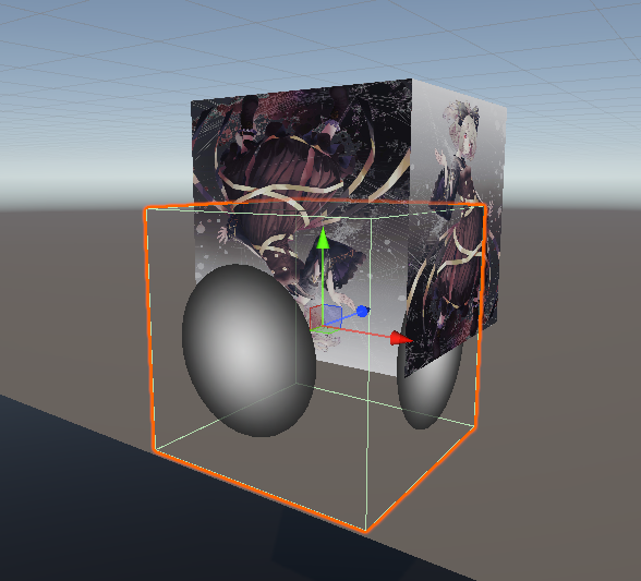
Dissolve Effect With Alpha Clip
게임에서 어떤 캐릭터가 죽을 때, 먼지처럼 사라지는 연출을 본 적이 있을 것이다.
이런 디졸브 연출은 구현 할 수 있는 여러가지 방법이 있을 수 있는데
Alpha Clip을 이용한 디졸브 이펙트를 구현 할 수 있다.
Cutoff Threshold를 이용해 오브젝트의 부분들을 Cull 할 수 있게 한다.
Shader "Lucid-Boundary/Tranparent_DissolveEffect"
{
    Properties
    {
        _MainTex ("Texture", 2D) = "white" {}
        _BaseColor("Base Color", Color) = (1, 1, 1, 1)
        _CutoffHeight("Cutoff Height", Float) = 0.0
        _NoiseScale("Noise Scale", Float) = 20
        _NoiseStrength("Noise Strength", Range(0.0, 1.0)) = 0.5
    }
    SubShader
    {
        Tags
        {
            "RenderType"="Opaque"
            "Queue" = "AlphaTest"
        }

        Pass
        {
            Cull Off

            HLSLPROGRAM
            #pragma vertex vert
            #pragma fragment frag

            #include "Packages/com.unity.render-pipelines.universal/ShaderLibrary/Core.hlsl"

            struct appdata
            {
                float4 vertex : POSITION;
                float2 uv : TEXCOORD0;
            };

            struct v2f
            {
                float2 uv : TEXCOORD0;
                float4 vertex : SV_POSITION;
                float4 positionOS : TEXCOORD1;
            };

            texture2D _MainTex;
            SamplerState sampler_MainTex;

            CBUFFER_START(UnityPerMaterial)
                float4 _MainTex_ST;
                float4 _BaseColor;
                float _CutoffHeight;
                float _NoiseScale;
                float _NoiseStrength;
            CBUFFER_END


            v2f vert (appdata v)
            {
                v2f o;
                o.vertex = TransformObjectToHClip(v.vertex.xyz);
                o.uv = TRANSFORM_TEX(v.uv, _MainTex);
                o.positionOS = v.vertex;
                return o;
            }

            // Generate a grid corner random unit Vector.
            float2 generateDir(float2 p)
            {
                p = p % 289;
                float x = (34 * p.x + 1) * p.x % 289 + p.y;
                x = (34 *  x + 1) * x % 289;
                x = frac (x / 41) * 2 - 1;
                return normalize(float2(x - floor(x + 0.5), abs(x) - 0.5));
            }

            float2 generateNoise(float2 p)
            {
                float2 ip = floor(p);
                float2 fp = frac(p);

                // calculate the nearest four grid point vectors
                float d00 = dot(generateDir(ip), fp);
                float d01 = dot(generateDir(ip + float2(0, 1)), fp - float2(0, 1));
                float d10 = dot(generateDir(ip + float2(1, 0)), fp - float2(1, 0));
                float d11 = dot(generateDir(ip + float2(1, 1)), fp - float2(1, 1));

                //Do 'smootherstep' between the dot products then bilinearly interpolate.
                fp = fp * fp * fp * (fp * (fp * 6 - 15) + 10);
                return lerp(lerp(d00, d01, fp.y), lerp(d10, d11, fp.y), fp.x);
            }

            float gradientNoise(float2 UV, float Scale)
            {
                return generateNoise(UV * Scale) * 2.0f;
            }

            float4 frag (v2f i) : SV_Target
            {

                float noiseSample = gradientNoise(i.uv, _NoiseScale) * _NoiseStrength;
                float noisyPosition = i.positionOS.y + noiseSample;

                if(noisyPosition > _CutoffHeight) discard;

                float4 col = SAMPLE_TEXTURE2D(_MainTex, sampler_MainTex, i.uv);
                float4 outputColor = col * _BaseColor;
                return outputColor;
            }
            ENDHLSL
        }
    }
}
무언가 어마어마하게 많아졌다.
이상한 수식들에 쫄지말고 차근차근 살펴보자.
v2f 구조체에 positionOS라는 이름으로 UV 채널을 하나 포함하고 있는데,
Vert Shader에서 볼 수 있듯이, View Space 내에서 포지션 값을 들고 가는걸 볼 수 있다.
중간 함수들은 일단 생략하고 Fragment Shader부터 보자.
uv를 이용해 넣은 float sample을 View Space에서 가져왔던 포지션과 더해주고 있다.
이름에서 볼 수 있듯이 noise라는 랜덤 값을 height 값과 더해줘서
해당 height가 Threshold보다 높으면 버려버리는 방식이다.
중간 함수들은 그저 noise를 생성 해준다는 걸 알 수 있다.
수식이 어려워보이면, 그냥 넘어가자. 이래뵈도 공식 문서에 나온 노이즈 함수이니까.
https://docs.unity3d.com/kr/Packages/com.unity.shadergraph@10.8/manual/Gradient-Noise-Node.html
Gradient Noise 노드 | Shader Graph | 10.8.0
Gradient Noise 노드 설명 UV 입력을 기반으로 그레디언트 또는 Perlin 노이즈를 생성합니다. 생성된 노이즈의 스케일은 Scale 입력에서 제어됩니다. 포트 이름 방향 Type 바인딩 설명 UV 입력 벡터 2 UV 입
docs.unity3d.com
https://en.wikipedia.org/wiki/Perlin_noise
Perlin noise - Wikipedia
From Wikipedia, the free encyclopedia Type of gradient noise in computer graphics Two-dimensional slice through 3D Perlin noise at z = 0 Perlin noise is a type of gradient noise developed by Ken Perlin in 1983. It has many uses, including but not limited t
en.wikipedia.org
문서에 따르면 Perlin noise 라고 한다.
83년도에 나온 오래된 논문으로부터 나온 노이즈인데
이런 논문들이 대부분 "Pseudo-Random" 랜덤 밸류를 들고온다.
하드코딩 되어있는 랜덤 밸류지만, 통계적으로 랜덤에 가까운이란 의미라고 한다.
어처피 컴퓨터 그래픽스란 현실을 만드는게 아니라 현실처럼 모방하는 것이다. 그런갑다 하자.
적어도, 앞으로 보게 될 수많은 HLSL 코드에 박혀있을 것이니
아 픽셀들에 노이즈를 생성하려는구나 하고 이해하면 된다.
결국 해당 예제의 의도는 Height 값이 Threshold에 따라 랜덤으로 사라지는 연출을 의도한 것이다.

Dissolve Effect In Shader Graph


일단 기본적인 세팅을 준비 해두자.
Noise 만들기

노이즈 노드는 Gradient Noise가 있다.
NoiseScale 값을 물려준다.
Remap 노드는 In 에 해당하는 범위의 값을, Out에 해당하는 범위의 값으로 선형 보간하는 방식이다.
Strength 값에 따라 Vector2의 범위는 (-x, x)로 점점 넓어지게 된다.
값을 늘려보면 Remap의 결과가 좀 강하게 바뀔 것이다.
Cutoff 하기
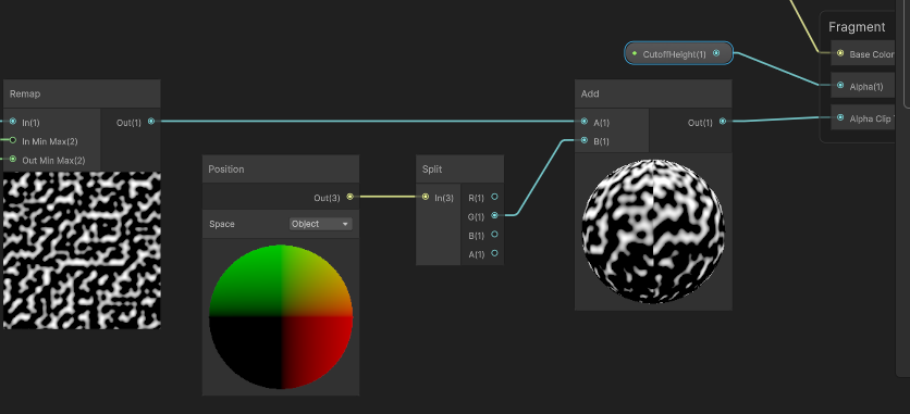
Remap의 결과인 노이즈는 Position.y 와 결합되어 y의 값에 따라 클리핑된다.
마치며
드디어 Shader의 기본적인 이론은 거의 끝났다.
나중에 포스팅할 Lighting 까지 하면, 이론적으로는 알건 다 아는 사람이 될 것이다.
'Game Dev > Unity Shader' 카테고리의 다른 글
| 13. Shader Keywords - 다니엘 릿 쉐이더 프로젝트 (0) | 2025.10.18 |
|---|---|
| 12. Dissolve Effect 개선하기, C# 코드와 상호작용 - 다니엘 릿 쉐이더 프로젝트 (0) | 2025.10.17 |
| 10. Transparency And Alpha - 다니엘 릿 쉐이더 프로젝트 (0) | 2025.10.17 |
| 09. Depth Buffer 심화 (3) - 다니엘 릿 쉐이더 프로젝트 (0) | 2025.10.16 |
| 08. Depth Buffer 심화 (2) - 다니엘 릿 쉐이더 프로젝트 (0) | 2025.10.16 |